With our testing period just around the corner, we’ve spent the last week setting up our equipment and making final preparations.
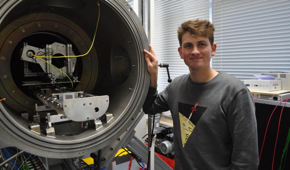
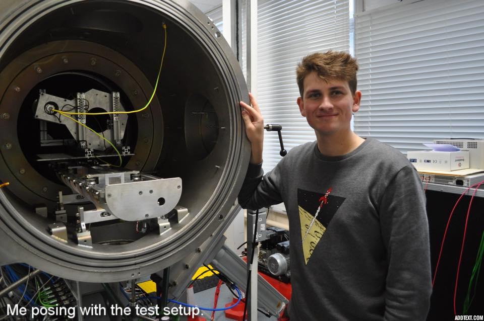
A quick introduction to our testing environment. We are using the vacuum chamber at the University of Southampton. This is in fact formed of one large, main chamber, and a smaller ‘hatch’ chamber. Each chamber can be sealed off from the other and separately depressurised. As opposed to the main chamber, which takes many hours to depressurise, the hatch chamber can be vacated in about half an hour. A rail system within the vacuum chamber allows a test item to be moved between the main chamber and the hatch chamber (this system is visible in both the photos below.) Thus, if any changes need to be made to the test setup, we can save ourselves a lot of time by pressurising only the hatch chamber, rather than the entire apparatus. This is especially useful in our case, as we are hoping to test several configurations of our neutraliser (different antennas and orifice sizes).
 Looking towards the hatch chamber.
 Looking from the hatch chamber.
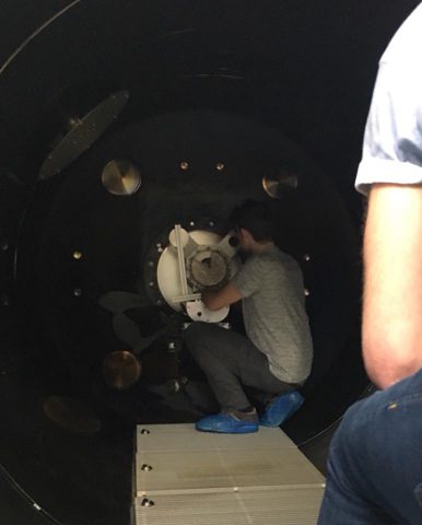
 After checking the fit of the interface plate, it became clear that the test setup was too large too fit through the passage between the two chambers (as seen below, this gives a scale of the size of the vacuum chamber). Although we would still be able to test our component, it would make our turnaround time between tests much longer and would reduce the amount of testing we could do.

Instead, we decided to remove one of the ‘ears’ of the existing design and drill new holes so that the plate could be mounted more horizontally. This was challenging, as we had to maintain a certain separation between the legs of the test equipment (so that we could mount it to the vacuum chamber rails), while also leaving clearance for all the attachment points to the plate. Fortunately, we were able to make these changes.
 Marking out the new holes.
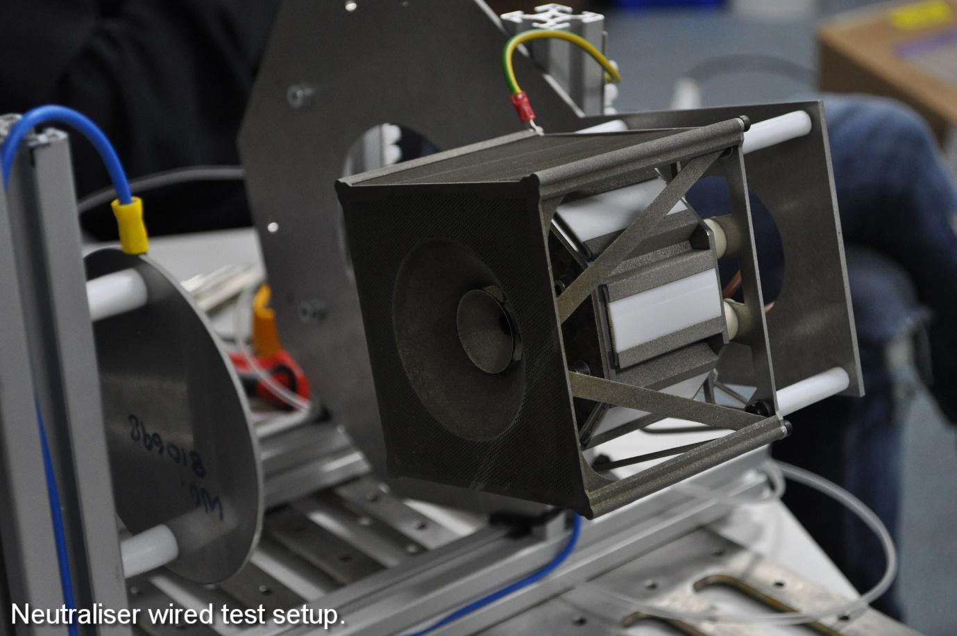
 The new test setup.
With the fitting issue resolved, our next task was to set up the electrical and propellant equipment needed for the test. For the electrics, we would need a high voltage power supply to our anode plate (which simulates the thruster beam), while the neutraliser chamber and the Faraday cage would both be grounded. The former was achieved by connecting the plate to a power supply, via a feed through on the side of the chamber (blue cable). The latter, by connecting the cables to the inside of the chamber, thus grounding the neutraliser (brown cables) and cage (yellow/green cable). We also set up some tubing which would provide argon gas (our fuel) to the neutraliser, again via the chamber feed (clear tubing). To prevent any cables snagging when moving the apparatus between the two chambers, we ran them along the test rig and cable tied them together.
Take a look at these photos of the setup:
Despite being prepared for testing with our side of the project, full installation of the microwave generator can’t take place without a working thruster. All the components for the thruster have not been completed yet, but by collaborating with the PhD student overseeing the thruster design, we’ve been able to produce a limited thruster which will hopefully operate sufficiently for the installation. This version of the thruster currently only has one grid attached, whereas the final design will have 3, but it already looks the part when mounted alongside the neutraliser!
 The thruster magnet rack being assembled.
 The overall thruster/neutraliser test setup.
 The thruster being mounted on the test plate.
Marcus Collier-Wright


